During my time researching show and ride control as well as chatting with some nice folks at places that do show control, I found out that there were a few ways they control the show.
One is with premade show specific controllers, like those made by my good friends at Alcorn Mcbride, and the other being Programmable Logic Controllers (PLCs).
I found PLCs to be incredibly fascinating as they seemed like a hybrid of microcontrollers with a programming language that is widely used that is unique to them called “ladder logic”.
Ladder logic was basically a visual digital logic like I had used in my undergrad studies in college but instead of basic logic gates you created your own using these visual relays, it is a lot of fun.
One of the coolest things I really loved about PLC programming was working with timing, it made it super easy and the various types of sensors and configurations you could setup with them was mind boggling.
I found some pretty great software to test myself on writing ladder logic programs and it woke up my digital logic brain really fast and I was off solving working puzzles in a shot.
I found out there are quite a few PLCs out there in active use in theme parks and decided I would start off with Allen Bradley Controllogix compatible controllers, mostly due to there abundance on ebay and easy to find programming software.
The project I wanted to do following solving all these fun logic control puzzles was to take a PLC and use it to control show elements.
I had an idea for a little diorama with a small projector that would loop a video of someone writing at a desk, when someone approached the desk it would detect that someone was close and then play a separate video where the person looks up and notices the person looking at the diorama. Then begins talking to them “oh hi, I didn’t see you there, would you mind if you held still so I could sketch a picture of you?” The person would sit back down at the desk and begin sketching. What would happen at that moment is that a hidden camera on the front of the diorama would take a photo of the person. The image would be run through a image manipulation filter that the camera is controlled by and produce an image that looks like a painting. Then after the sketch was processed the person would pull away a curtain and show you a finished picture of yourself. Then say “Here you go, I hope you like it! ” the person would return to there desk and then go back to the original video loop where it looks like they are just sketching.
I decided that since I didn’t have a computer to do video editing at the time I would at least complete the PLC portion with the sensors and using indicator lights as well as a video signage/kiosk player displaying images in place of video.
I found an Allen Bradley Micrologix 1100 controller with a questionable display, fixed it, and found a few lots of buttons and indicator lights and a power supply to power the whole lot.
The Roku video and image player that is used for Kiosks and signage would be my triggerable video output. I read the manual of the Roku player carefully and sketched out my circuit and made sure all my control voltages were compatible with both my PLC as well as the Roku. I then began the process of writing the ladder logic code for the sensor, the video output trigger, and the timing. When I was finished I had a program that worked exactly how I wanted it to. Granted I didn’t have cool videos to show or a diorama built but functionally all I would have to do is replace the images with videos and I would have a completely working version! This was pretty awesome! These controls were so incredibly useful and amount of things you could do with them makes my brain lock up with infinite possibilities.
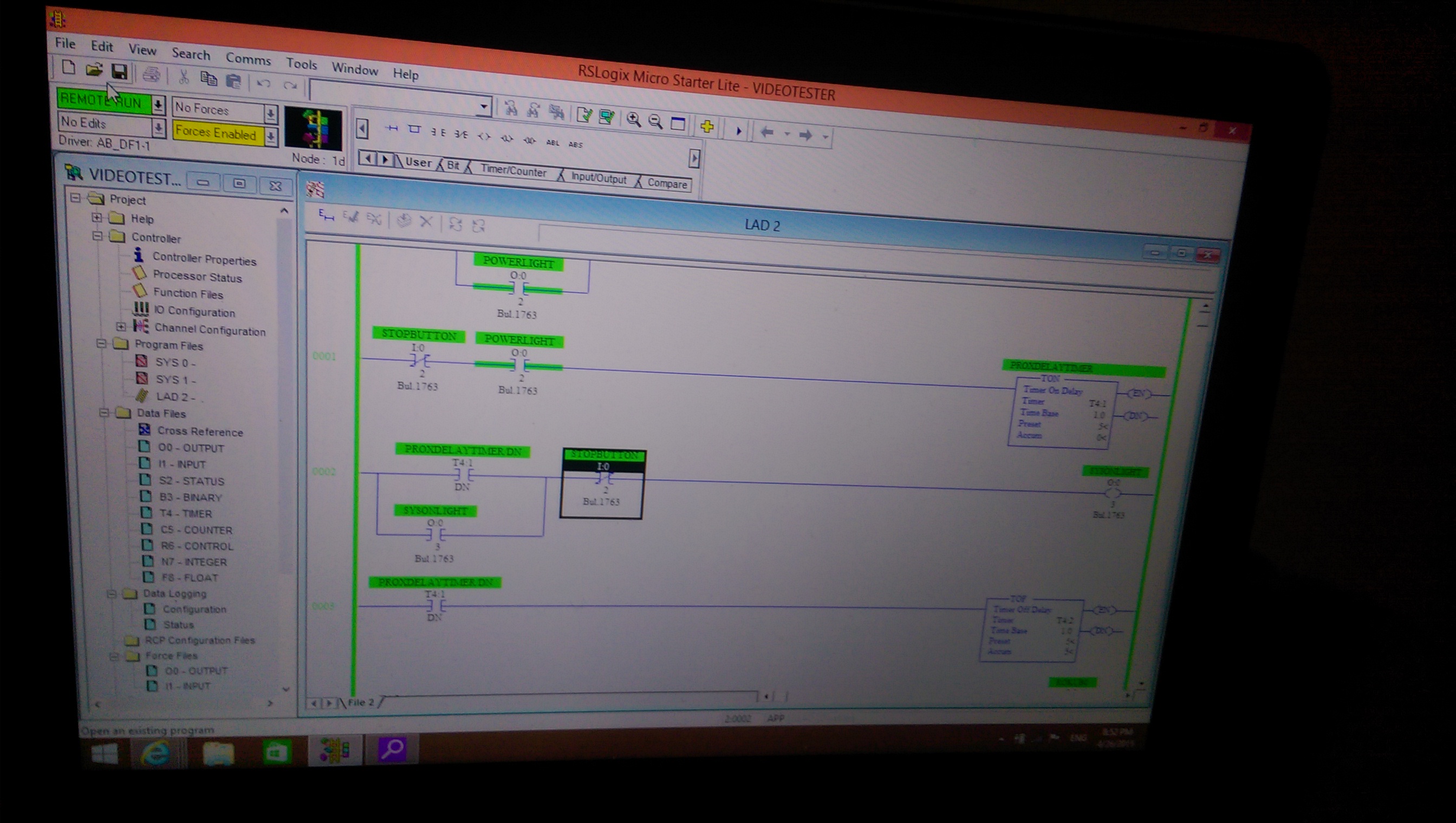
Here is some of the ladder logic I used for the timing and sensors and output.
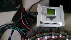
Here is the micrologix 1100 I used.
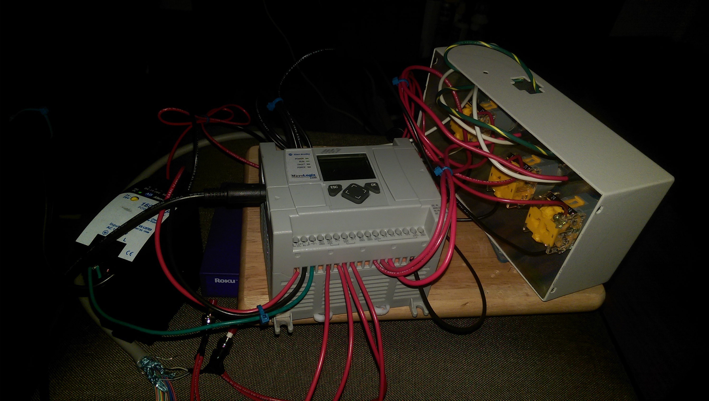
Wiring up the controller to the control panel
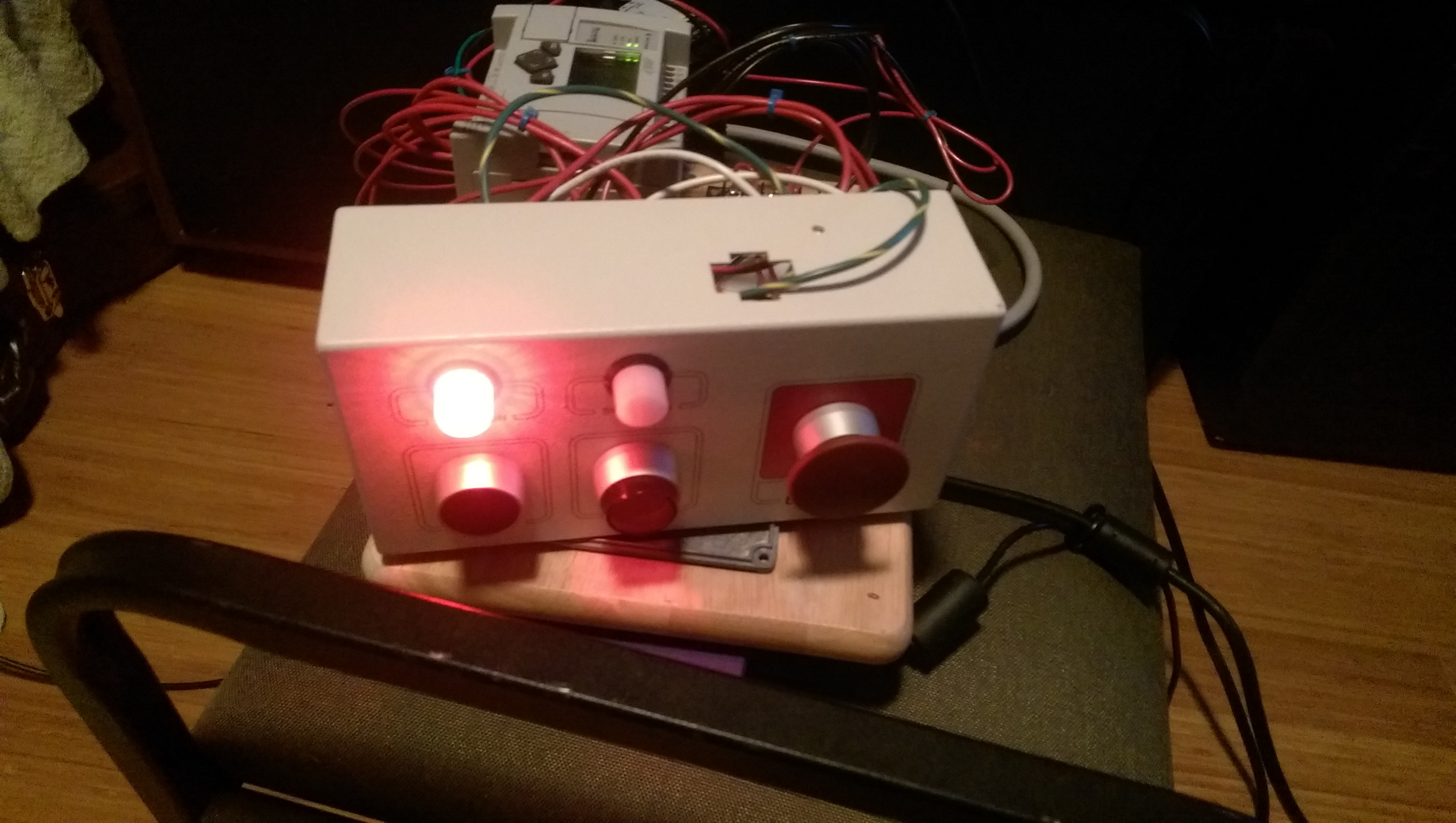
Running the program and displaying the images.
I have a video of it working but I am still searching for it!
Here is the original conceptual sketch I did of this idea.
The flow chart of how program would work and where the video would play which loop.
This is my PLC wiring diagram for the sensors and buttons and my video looper triggers.
Here is the video looper CSV file I made for the different states I wanted it to react to and what videos it should play.
Here was my equipment list for the build